Lesson 3: Getting Serial - writing to and from our board
Communication - in Both Directions!
Lesson 3: Getting Serial - writing to and from our board
Lesson 7 - Real world data at your fingertips: Light, Ultrasonic Motion and more...
Lesson 8 - Build your own BLE ultrasonic motion detector for under $USD30
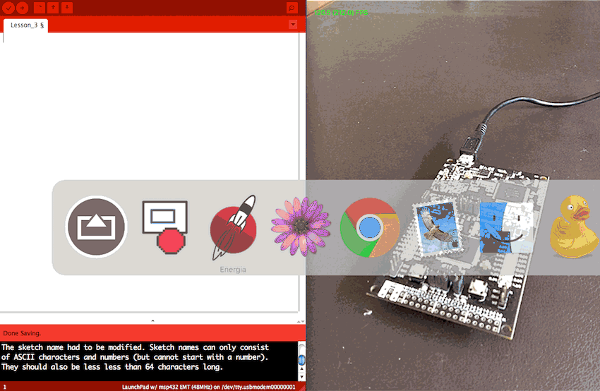
The serial port is a great way to communicate with your board, and to receive feedback from your sketch. The standard serial port for the LaunchPad is the USB port, and Energia offers a "serial monitor" for watching what is happening. Initialising the serial port is easy - just add Serial.begin() to your setup routine, and give a baud speed (9600 seems fairly standard, and for Energia the fastest is 115200).
Let's add serial support to a simple button and LED sketch.
int buttonState = 0;
void setup() {
pinMode(RED_LED, OUTPUT); pinMode(PUSH1, INPUT_PULLUP); Serial.begin(9600); }
void loop() { buttonState = digitalRead(PUSH1);
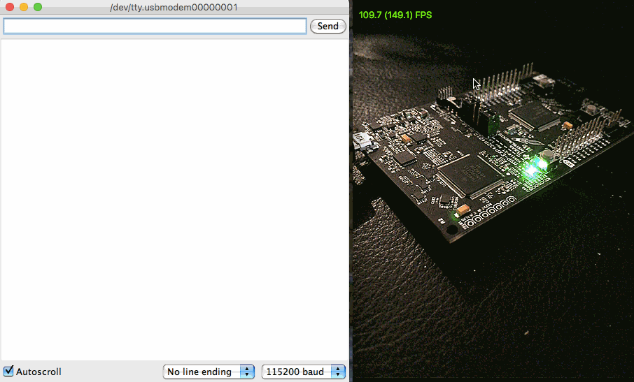
if (buttonState == LOW) {}digitalWrite(RED_LED, HIGH); Serial.println("Button 1"); Serial.println("Red LED");} else {digitalWrite(RED_LED, LOW);}Try changing the baud rate from 9600 to 115200: what do you notice? (You will need to change the dropdown menu at the bottom right of the serial monitor window to the correct rate). The response time should be faster, but otherwise all still works.
Change Serial.println to just Serial.print - "println" forces a new line for each statement. "print" runs the strings together.
So in this way, we can use the Serial port to give us a running commentary on our sketch - very useful when debugging and trying new things!
|
Writing TO the board
|
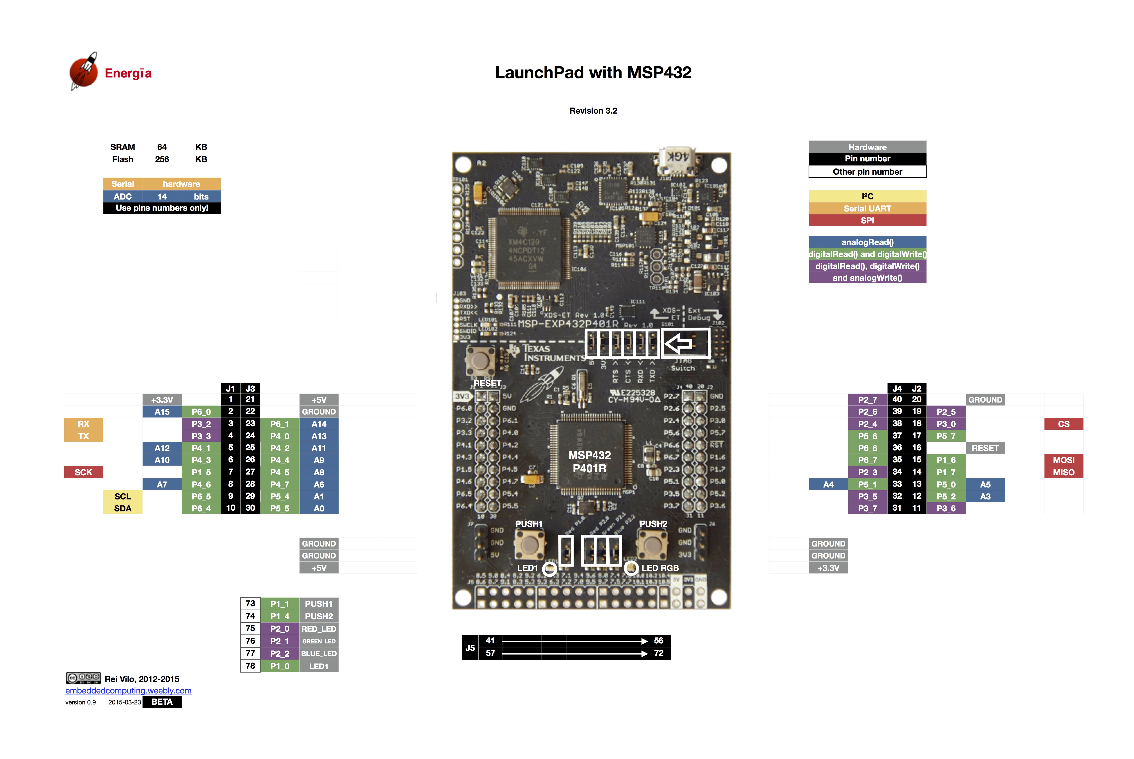
MSP430 sketch int buttonState1 = 0; int buttonState2 = 0; void setup() { pinMode(RED_LED, OUTPUT); pinMode(GREEN_LED, OUTPUT); pinMode(PUSH1, INPUT_PULLUP); pinMode(PUSH2, INPUT_PULLUP); Serial.begin(115200); } void loop() { buttonState1 = digitalRead(PUSH1); buttonState2 = digitalRead(PUSH2); char recvChar; if(Serial.available()){ recvChar = Serial.read(); Serial.println(recvChar); } switch(recvChar) { case '1': buttonState1 = LOW; break; case '2': buttonState2 = LOW; break;} if (buttonState1 == LOW) { digitalWrite(RED_LED, HIGH); Serial.println("Red LED ON"); delay(1000); digitalWrite(RED_LED, LOW); digitalWrite(GREEN_LED, HIGH); Serial.println("Green LED ON"); delay(1000); digitalWrite(GREEN_LED, LOW);} if (buttonState2 == LOW) { digitalWrite(GREEN_LED, HIGH); Serial.println("Green LED ON"); delay(1000); digitalWrite(GREEN_LED, LOW); digitalWrite(RED_LED, HIGH); Serial.println("Red LED ON"); delay(1000); digitalWrite(RED_LED, LOW); delay(1000);} } |
Hacking the Hub™
|
|

Home ← TI-Nspire Scripting HQ ←STEM HQ ← Getting Started with TI LaunchPads ← TI LaunchPad Lesson 3